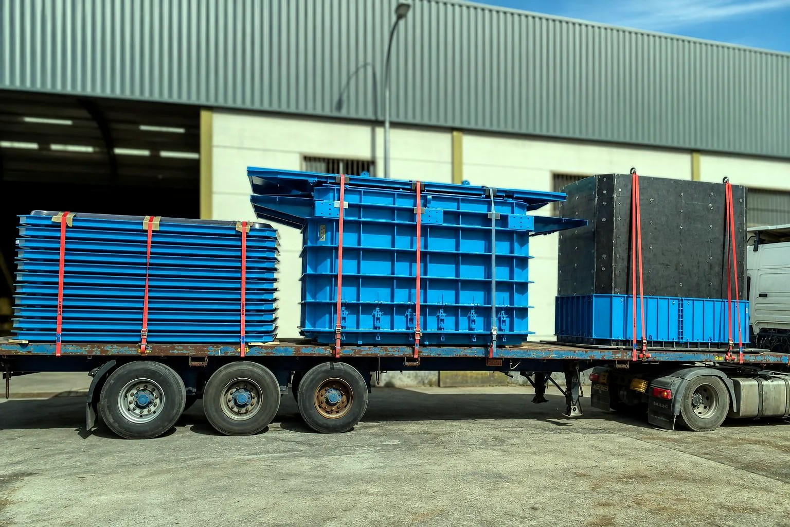
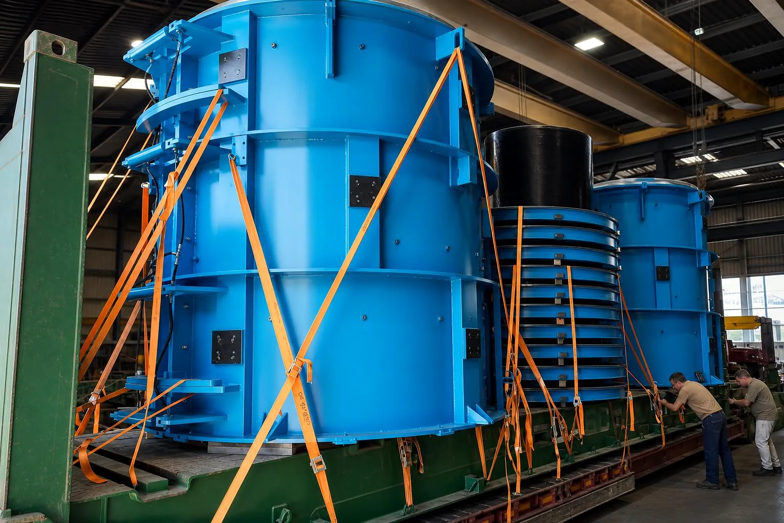

Custom-made steel moulds for producing concrete jacking pipes with stable geometry, secure closing and cleaner demoulding cycles. Designed to work with precision, strength and production continuity.
Each assembly is manufactured to respond to a specific production need: stable geometry, safe handling, controlled compaction and clean demoulding.


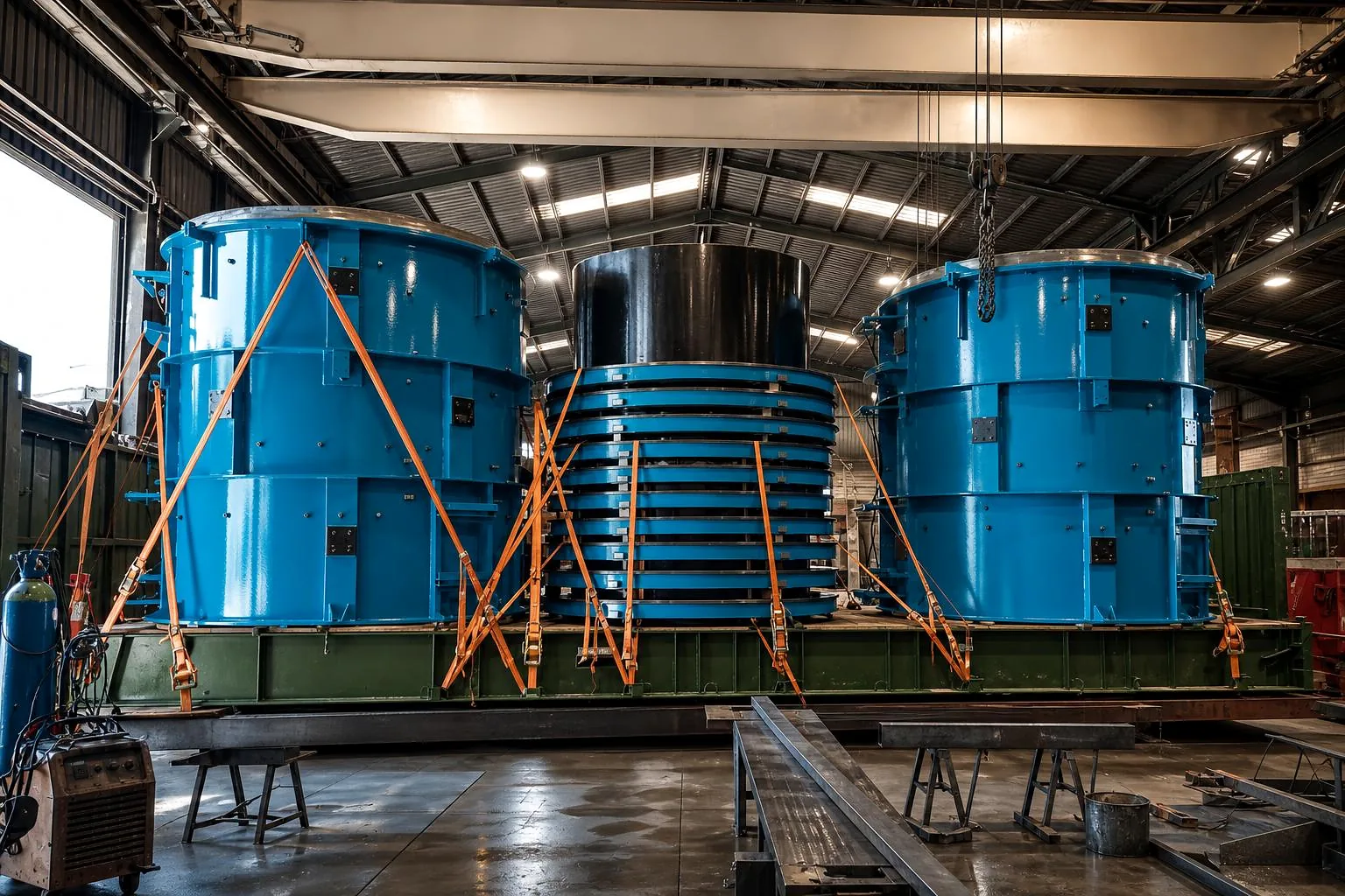
The important thing is not to list components as another specification sheet. Here the focus is how core, shell, table, rings and closures relate so the pipe comes out with accurate dimensions, stability and controlled demoulding.

The assembly defines internal and external geometry, supports casting, maintains stability and allows opening or extraction without damaging the part.
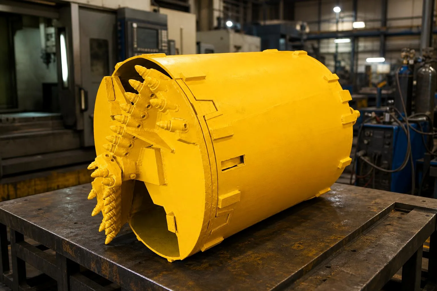
Removable element that defines the pipe’s internal diameter and conditions demoulding.
External structure that gives the cylindrical shape and allows controlled opening of the mould.
Base, rings and supports distribute weight, stabilise the assembly and facilitate handling.
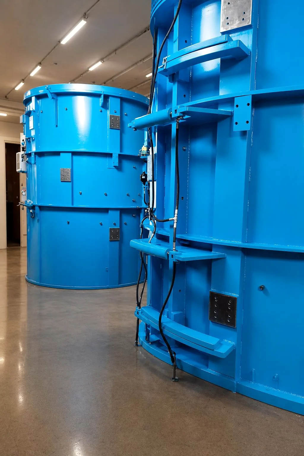
Mechanical or hydraulic systems that join, lock and release the assembly with precision.
Dimensions, thicknesses and handling are adjusted to drawings, workshop and real production conditions.
Each mould is defined according to drawing, sample or production need. Dimensions, component assembly, handling, supports, closures and finish are reviewed before manufacturing.
Diameter, length and configuration according to drawing, sample or production need.
Internal core, jackets, rings, closures, supports and handling elements defined by real use.
Reinforced steel structure to control deformation, opening and closing.
Surface protection, industrial paint and preparation for transport or assembly.
Review of fits, access, lifting points and critical areas before delivery.
Repair, modification or evolution of existing moulds when the project requires it.
The process combines technical reading, steel manufacturing and final adjustment so the mould arrives ready to work in real production cycles.
Dimensions, intended use, available machinery and handling constraints are reviewed.
How the core, rings and jackets open, close, support and are handled is defined.
The workshop resolves welding, rigidity, finish and working points before delivery.

Closures and supports designed for repetition, not just for a single isolated part.
Attention to deformation, demoulding, maintenance and safe handling.
Possibility of working from a drawing, existing part or already detected production problem.
Other Relente manufacturing lines for precast concrete and deep drilling.
We design and manufacture jacking pipe moulds for dry-cast concrete and concrete pipes, with stable diameter, defined ends, clean thrust faces and an opening system designed to repeat production cycles without punishing the workshop.
When the manufacturer needs to produce pipes for trenchless installation, the mould must help control diameter, length, thicknesses, joint housing and thrust faces.
Many enquiries arise from wear, deformation, awkward closures, slow extraction or parts that do not come out clean. In those cases, assembly design matters more than the material itself.
A standard pipe is not the same as a series with ferrule, rubber gasket, thrust ring, spigot/bell or jobsite dimensional requirements.
It can also start from a mould already in use: core, shell, supports, rings, reinforcement and handling are reviewed to extend service life or improve production.
The jacking pipe works in a demanding installation: it receives thrust during execution, must maintain alignment and needs well-resolved ends. That is why the mould is designed from the final part and the full manufacturing cycle, not only from an external dimension.
The core defines the interior; the shell controls the exterior; rings and auxiliary tooling condition the ends, joint and repeatability between cycles.
Diameter, thickness, length, taper, support and tolerances must be maintained even when the mould undergoes vibration, handling, cleaning and continued use.
A good mould does more than shape the part: it must open and close safely, allow concrete casting, facilitate extraction, reduce downtime and withstand real maintenance.
A jacking mould should not be treated as a generic shell. Pipe geometry, thrust, handling and production pace require the complete assembly to be designed with workshop judgement.
To produce a specific horizontal jacking pipe, the mould must control diameter, length, thickness, ends and bearing surfaces with repeatability.
For a concrete jacking pipe, the assembly must resolve shell, core, closures, rings and demoulding without losing stability during continuous work.
The pipe ends, joint housing, support, thrust ring and load distribution are areas where the mould must maintain precision.
When the problem is extraction, adhesion, deformation or jacking pipe finish, geometry, opening system, supports and work sequence must be reviewed.
Interior, exterior, shell, core, rings and auxiliary tooling define the real pipe geometry and condition clean demoulding.
Specific case when the jacking mould already exists but has play, worn closures, deformation, wear or handling problems.
The clearer the part and process are, the more precise the technical proposal can be.
Useful information to prepare dimensions, drawings, photos of the existing mould or data about the pipe to be manufactured.
The jacking pipe must withstand thrust forces and maintain geometry in a trenchless installation. The mould requires more attention to ends, bearing faces, joint, load distribution and dimensional repeatability.
Yes. The starting point is the jacking pipe dimensions, thickness, joint type, end geometry, thrust faces, manufacturing process and production pace.
Core, shell, closures, rings, supports, tapers, contact surfaces and opening sequence. If one of these parts is not properly resolved, the cycle slows down or the part may come out with defects.
It can be studied. If the mould already works but causes problems, deformation, play, wear, closing, handling, rigidity and real adaptation possibilities are reviewed without compromising the part.
Drawings, dimensions, photos of the mould or part, diameter, length, joint type, production system, current issues and objective: manufacture from scratch, repair, adapt or increase performance.